
Implement a multi-stage RC (Remote-Controlled) signal converter and a dashboard for small-robotics and ESC (Electronic Speed Controller) testing
Full Typed report provided dtope004-dres002_custom_lab_report.pdf
- Microcontroller: Raspberry Pi Pico 2W (x2), pinout, C/C++ SDK
- FPGA: iCE Sugar Pro, pinout
- Display: 4.3 inch TFT LCD 480*272 resolution RGB565 and PMOD
- Wireless input Microcontroller: ESP32-S3 LoRA Development Board (ESP32-S3-LR1121-HF), documentation, custom firmware
- Backup plan if the Development board doesn't work, RadioMaster ELRS receiver (Not used)
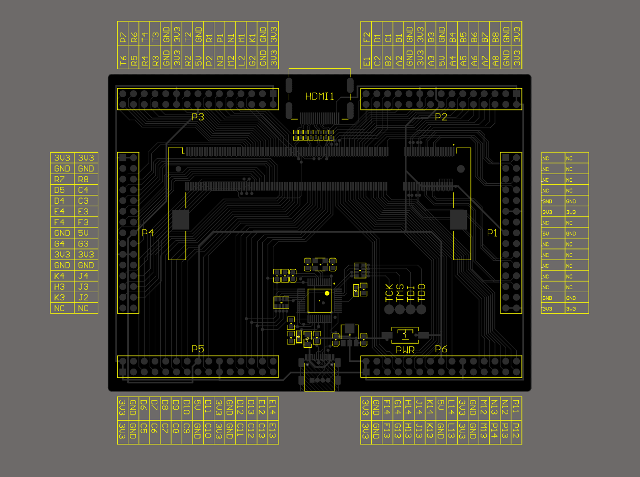
- For text processing from Pico to FPGA, we are using an framebuffer with LVGL provided to us
- We used a custom ELRS reciever PCB which had to have its own custom ELRS configuration made by Troy.
Codebase in icesugar-pro-framebuffer/sw/
- UART1 - Receives ELRS from ESP32-S3 LoRA Dev Board
- GP15 - Sends Display Data for Pico[1]
- SPI0 - Sends Display Data for FPGA for LCD
- Displays Channel data, using LVGL, displays the 8 channels on the FPGA's Display
- GP15 - Encodes channel data into PPM Signal to Pico[1]
- Decodes PPM from Pico[0] and splits it across 8 PWM Channels
Codebase in icesugar-pro-framebuffer/hw/
- Runs icesugarpro Framebuffer
Expected progress for the project
-
- Program ELRS input to PPM output in the Pico (First half done)
-
- This PPM output goes to the FPGA
-
- Pico SPI0 CRFS -> PPM to FPGA
-
- Pico SPI1 CRSF -> Channel Values to FPGA-Display (done)
-
- FPGA -> 2 channels of PWM
pip install pyserial- Locate the Pico's serial
ls /dev/cu.usbmodem11* - Example for my machine:
python3 -m serial.tools.miniterm /dev/cu.usbmodem113401 113200