ESP32 driven macro keyboard built for personal use but documented for the sake of open source development.
This is a project born out of personal necessity to have a dedicated programmable macro keyboard on my desk which I can control easily and bind functions I use a lot to buttons of my own choice. I have made a similar project ~5 years ago which featured an arduino pro micro, 8 buttons, encoder, rgb leds and oled screen. This project aims to solve my main problem with that board: the wire going from the arduino to my PC.
By making this new project use an ESP32-C6 I will try to add a lot more functionality to the systems than was previously possible. My intent for this project is the ability to support multiple use cases, either directly connected to a PC, or by having it connected to a network where it will be able to connect to home assistant.
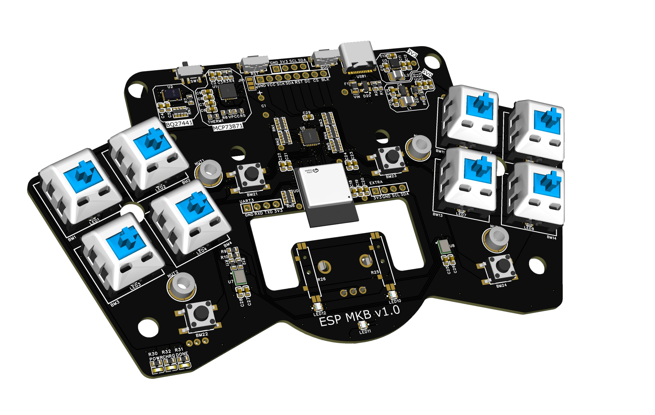
The main SOC is an ESP32-C6-Mini-1-N4. By using this specific ESP32 I will not only get WIFI+BT but also gain the option to later on include matter support and other cool stuff. The hardware components I have included in this first revision are the following:
- ESP32-C6-Mini-1-N4
- Reset and boot mode select buttons
- Multiple display options:
- SPI display option (1.69" 280x240 standard)
- UART display option (standard 1.3" I2C oled)
- USB-C
- TCA8418 button matrix IC
- 8x Kailh hot swappable cherry style sockets for cherry MX style switches
- 4x simple push buttons
- 2x short analog potmeters
- 1x encoder
- 18x RGB LED (XL-1615RGBC-WS2812B on top side / 5050 WS2812B on bottom)
- BMS system consisting of:
- MCP73871 Charge controller (Vout = Vbat (~3.7v) or Vout = Vusb (5.0v) when charging)
- BQ27441 Fuel gauge
- single 18650 battery holder
- Voltage regulation happens after MCP73871:
- TPS63051 3.3v buck-boost regulator (Vin min = 2.5v - Vin max = 5.5v)
- TPS613222 5.0v boost regulator (Vin min = 0.9v - Vin max = 5.5v)
| IO PIN | Function | Detail |
|---|---|---|
| IO00 | SPI SDA | |
| IO01 | SPI SCK | |
| IO02 | POT 1 | Analog |
| IO03 | POT 2 | Analog |
| IO04 | SPI DC | |
| IO05 | SPI RES | On rev 0 board SPI screen needs this pin to be used as SPI_BL |
| IO06 | TCA8418 INTERRUPT | Pullup 10K to 3v3 |
| IO07 | TCA8418 MATRIX RESET | Pullup 10K to 3v3 |
| IO08 | LED DATA | Pullup 10K to 3v3, Mistake on Rev 0: Ldata needs pullup to 5V0. Cut trace on rev 0 to disable pullup |
| IO09 | SPI BL | Rev 0 mistake: Can not be used as SPI BL in combination with Boot mode on IO9 |
| IO12 | UD- | |
| IO13 | UD+ | |
| IO14 | I2C SDA | Pullup 10K to 3v3 |
| IO15 | I2C SCL | Pullup 10K to 3v3 |
| IO16 | ENCODER A | Pullup 10K to 3v3 |
| IO17 | ENCODER B | Pullup 10K to 3v3 |
| IO18 | SPI CS | |
| IO19 | CHARGING Y/N | MCP73871 Pullup 10K to 3v3 |
| IO20 | BATTERY MEASURE | BQ27441 Pullup 10K to 3v3 |
| IO21 | I2S WS | |
| IO22 | I2S BCLK | |
| IO23 | I2S DATA |
ESP32C6, resistor networks, switches, communication buses and mounting hardware:

Power supply, battery management system and USB connection and voltage regulation

Main IO
