
Dual-motor BLDC / FOC controller. Compatible with ODrive 3.5 and SimpleFOC.
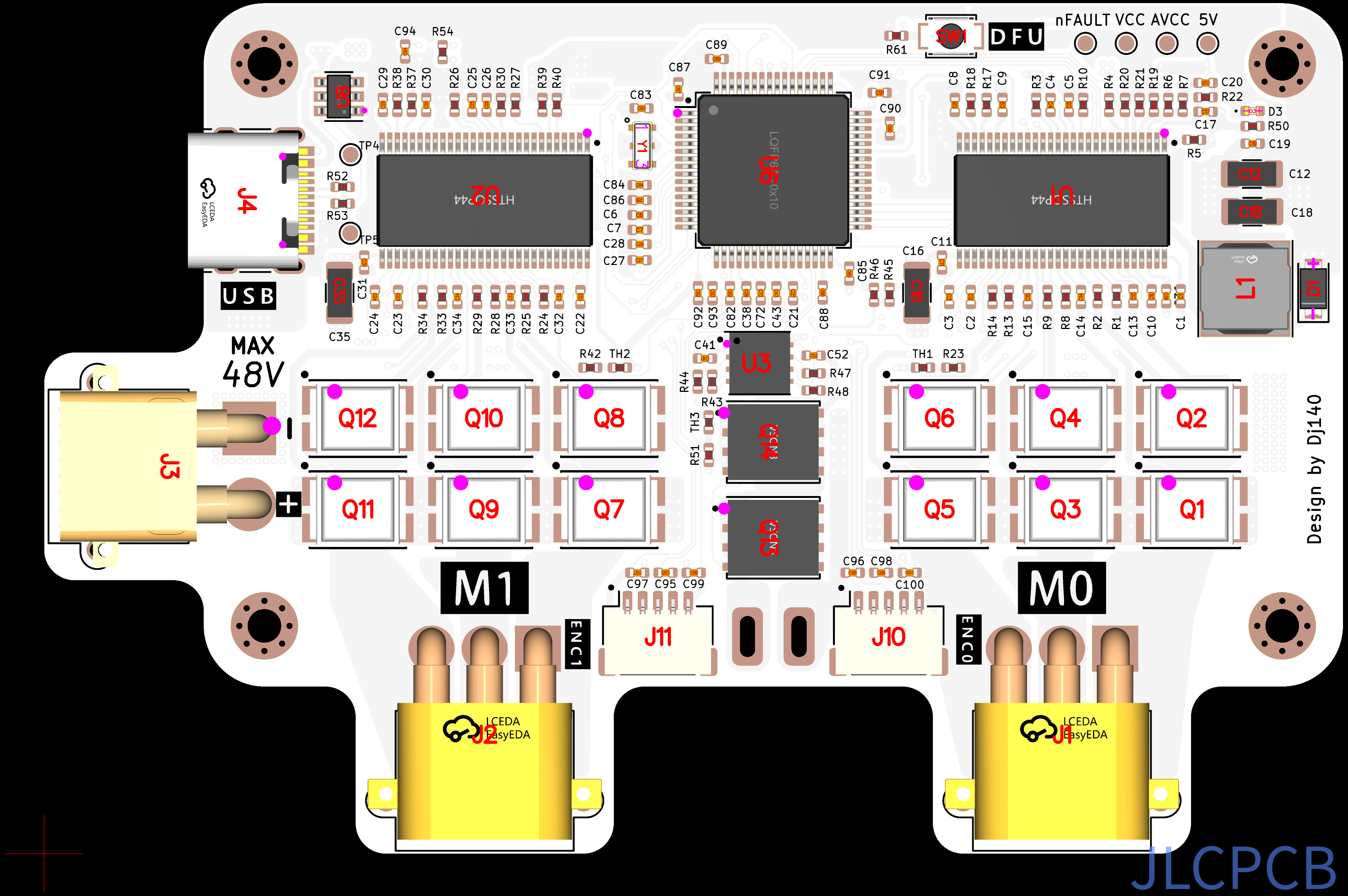
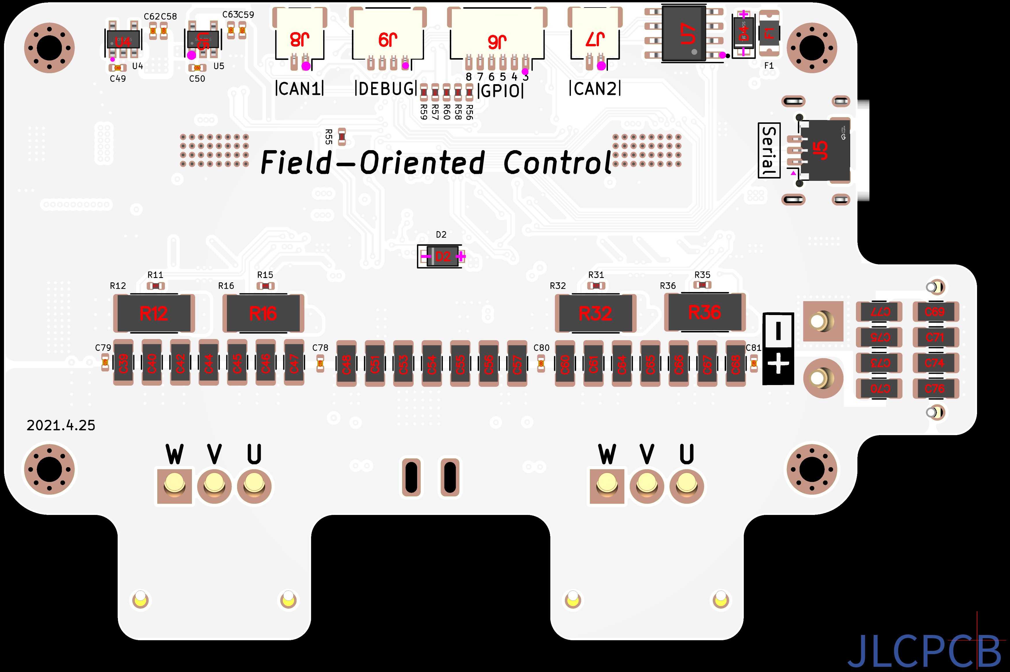
| Motor channels | 2 (M0, M1), 3-phase each |
| MCU | STM32F405RGT7, LQFP-64, 8 MHz ceramic resonator (Y1) |
| Gate drivers | 2 × DRV8301 (U1 = M0, U2 = M1), SPI-configured |
| Power stage | 12 × IRF7480M DirectFET N-MOSFET (6 per motor) |
| Current sense | 4 × 0.5 mΩ 2512 shunts (R12, R16, R32, R36), DRV8301 amplifiers |
| Supply | XT30 (J3), silk-marked MAX 48 V |
| Bulk capacitance | 10 µF 50 V 1206 array on bottom side |
| Logic supply | 5 V from DRV8301 (U1) buck (L1, D1); 3.3 V from U4 (SPX3819); 3.3 VA analog from U5 (LP5907) |
| USB | USB-C (J4), USBLC6-2SC6 ESD (U8); VBUS via F1 (500 mA) and D4 into +5 V |
| CAN | SN65HVD232 transceiver (U7), two connectors (J7, J8) |
| Auxiliary half-bridge | Q13, Q14 (CSD18540Q5B), LM5109B driver (U3); AUX_H / AUX_L from MCU; switch node HS on pad H6 |
| Temperature | 3 × 10 k NTC (TH1–TH3): M0_TEMP, M1_TEMP, AUX_TEMP |
| PCB | 4 layers, 1.6 mm, approx. 85.5 × 56 mm, 4 × mounting holes |
| Assembly | JLCPCB, both sides |
Firmware is not included in this repository.
| Ref | Silk | Type | Pins |
|---|---|---|---|
| J3 | MAX 48V | XT30PW | 1 GND, 2 VDC |
| J1 | M0 | MR30PW 3-pole | phases A, B, C |
| J2 | M1 | MR30PW 3-pole | phases A, B, C |
| J10 | ENC0 | JST SH 5-pin | 1 GND, 2 +5 V, 3 A, 4 B, 5 Z |
| J11 | ENC1 | JST SH 5-pin | 1 GND, 2 +5 V, 3 A, 4 B, 5 Z |
| J4 | USB | USB-C | USB 2.0, DFU / serial via STM32 |
| J5 | Serial | JST SH 3-pin | 1 GPIO_1, 2 GPIO_2, 3 GND |
| J6 | GPIO | JST SH 6-pin | 1–6 = GPIO_3 … GPIO_8 |
| J7 | CAN2 | JST SH 2-pin | 1 CAN_H, 2 CAN_L |
| J8 | CAN1 | JST SH 2-pin | 1 CAN_H, 2 CAN_L |
| J9 | DEBUG | JST SH 4-pin | 1 +5 V, 2 SWDIO, 3 SWCLK, 4 GND |
Bottom side also has solder pads for power (+ / −) and for each motor (U, V, W).
- SW1 (DFU): pulls BOOT0 to 3.3 V. Hold while powering to enter the STM32 DFU bootloader.
- D3: green LED.
- Test pads (top, right): nFAULT, VCC, AVCC, 5V.
- TP4, TP5: test points near J4.
Open_Drive_Schematic.pdf. KiCad sheets in bldc_motor_cntroller/:
| Sheet | Contents |
|---|---|
bldc_motor_cntroller.sch |
Top level |
microcontroller_interface.sch |
STM32F405 |
motor_driver.sch |
M0 DRV8301 and power stage |
motor_driver2.sch |
M1 DRV8301 and power stage |
power_management.sch |
Buck, LDOs, auxiliary half-bridge |
io_interface.sch |
USB, CAN, encoders, GPIO, debug |
bldc_motor_cntroller/
  *.sch, *.kicad_pcb, *.pro   KiCad project
  outputs/gerbers/            Gerber and drill files
  assembly/                   BOM and placement (KiCad export)
  production/                 JLCPCB BOM, placement, netlist, order zip
  bom/ibom.html               Interactive BOM
  images/                     Board renders
Open_Drive_Schematic.pdf
- Upload
bldc_motor_cntroller/outputs/gerbers/(orproduction/bldc_motor_cntroller.zip) to JLCPCB, 4 layers, 1.6 mm. - Enable assembly, both sides. Upload the BOM and positions files from
production/. - Check part rotation in the JLCPCB PCBA viewer before ordering. Rotation of SW1 and U4 differs from the KiCad export.
Based on X_driver by Dj140, which is based on the ODrive 3.5 schematic.
GPL-3.0. See LICENSE.